
LED AND SWITCH INTERFACE
💡 LED and Switch Interface with Arduino – Short Note
Overview:
Interfacing an LED and a push-button switch with Arduino allows you to control the LED using the button. This is a basic yet essential exercise in understanding digital input and output in Arduino.
⚙️ Required Components:
Arduino Uno (or any board)
LED (any color)
- 1 × Push button
220Ω resistor (to limit current)
Breadboard and jumper wires
🔌 Circuit Diagram:
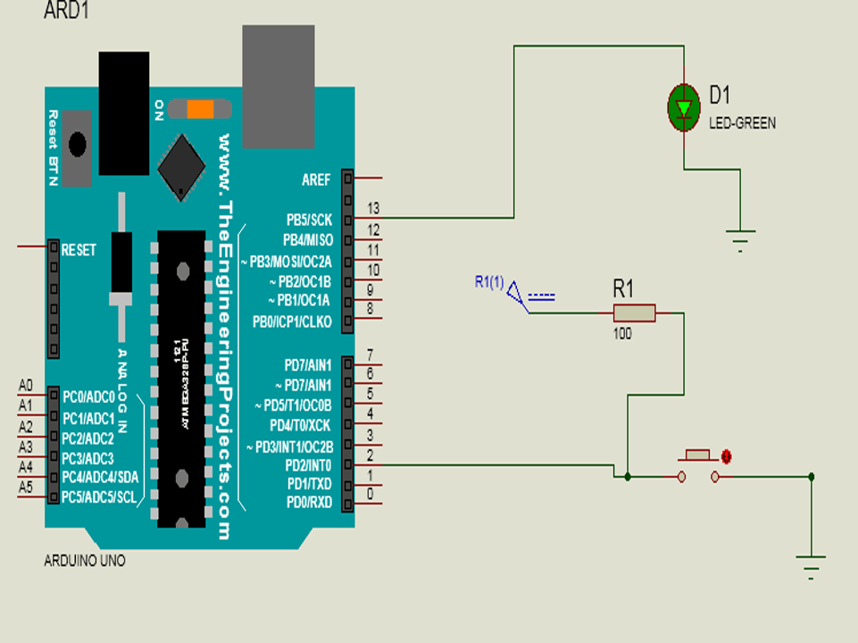
| Component | Connection |
|---|---|
| LED (anode) | Arduino digital pin (e.g., pin 13) |
| LED (cathode) | 220Ω resistor → GND |
| Push button | One side to digital pin (e.g., pin 2) |
| Other side | GND through 10kΩ resistor (pull-down) and also to 5V when pressed |
📝 Sample Arduino Code:
🧠 Key Points:
digitalRead(pin) reads the current status of the button (HIGH or LOW).
Use a pull-down resistor to ensure the input pin doesn’t float (avoid random behavior).
This project demonstrates how input (switch) can control an output (LED).
📞 For More Details & Project Support:
Power Integrated Solutions
Networks | Electronics | Home Automation | Water Automation | IoT | PLC | Embedded | DBMS
📍 Location:
10A/3, Radhakrishnan Colony,
Sasthri Road, Tennur,
Tiruchirappalli, Tamil Nadu – 620017
📧 Email:
📱 Phone / WhatsApp:
+91 76393 85448
+91 82488 85959
🌐 Let’s Build the Future with Innovation in Education & Technology!