
SINGLE LED BLINK
💡 LED Interface with RP2040 – Short Note
Overview:
An LED (Light Emitting Diode) is a basic output device used with RP2040 to visually indicate status, signals, or logic. It glows when current flows through it in the forward direction.
⚙️ Required Components:
R2040 (or any board)
LED (any color)
220Ω resistor (to limit current)
Breadboard and jumper wires
🔌 Circuit Diagram:
📝 Notes:
Pin(2, Pin.OUT)sets GPIO2 as an output pin.led.toggle()is a convenient way to flip the state without checking it first.You can replace
2with any valid GPIO pin like3,15, etc., depending on your wiring.
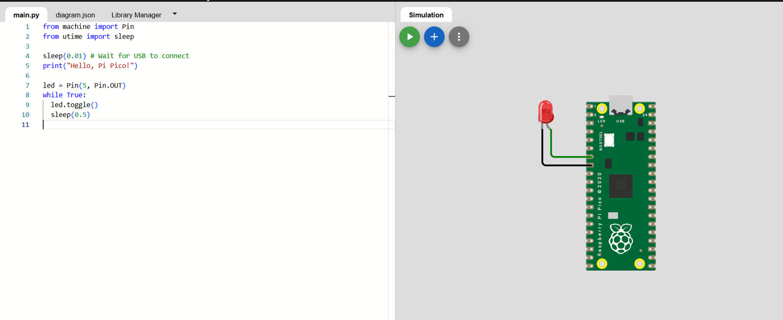
✅ Wokwi Setup Steps
Go to Wokwi: https://wokwi.com
Click “New Project” → Select Raspberry Pi Pico (Python)
🔌 Connect LED in Simulator
In Wokwi circuit editor, connect as follows:
GPIO2 → Anode (+) of LED (with 220Ω resistor)
Cathode (–) of LED → GND
🛠️ Customizing the Simulation
If you’d like to modify the GPIO pin or adjust the blink interval:
Click the “Edit Code” button in the simulation.
Change the
Pin(5, Pin.OUT)line to use your desired GPIO pin (e.g.,Pin(2, Pin.OUT)).Adjust the
sleep(0.5)value to set a different blink interval (e.g.,sleep(1)for a 1-second interval).Click the “Start Simulation” button to see the changes in action.
📝 Sample Code:
🧠 Key Points:
Always use a resistor to prevent LED damage.
led.toggle() turns ON the LED.
LEDs are polarity sensitive (must be connected the right way).
Multiple LEDs can be connected to different pins for patterns.
📞 For More Details & Project Support:
Power Integrated Solutions
Networks | Electronics | Home Automation | Water Automation | IoT | PLC | Embedded | DBMS
📍 Location:
10A/3, Radhakrishnan Colony,
Sasthri Road, Tennur,
Tiruchirappalli, Tamil Nadu – 620017
📧 Email:
📱 Phone / WhatsApp:
+91 76393 85448
+91 82488 85959
🌐 Let’s Build the Future with Innovation in Education & Technology!