
POWER QUALITY IMPROVEMENT USING ACTIVE FILTERS
ABSTRACT:
Poor quality of electric supply is normally caused by power line disturbances such as transients, notches, momentary interruptions, voltage sag and swell, over-voltage, under-voltages and harmonic distortions. Filters are used for improving the power quality. Active and Passive filters eliminate major fluctuating factors. Hybrid filters are the combination of active and passive filters. Conventional Active Filtering using PLL also reduces the harmonics. Total Harmonic Distortion (THD) can be reduced by implementing combination of active and passive filters. To design a hybrid power filter to reduce the harmonics for enhancing the quality of power.
OBJECTIVE:
The objective of Power Quality Improvement Using Active Filters is to design and develop an efficient and effective active filter system that can mitigate power quality issues such as harmonic distortion, voltage sag, and flicker, thereby improving the overall power quality and reliability of the electrical grid. This is achieved by using advanced control algorithms and power electronic devices to actively filter out distortions and compensate for voltage fluctuations, ensuring a stable and clean power supply to sensitive loads and equipment.
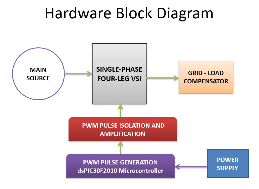
BLOCK DIAGRAM:
WORKING:
- This paper proposes a single phase grid tied voltage sourced inverter (VSI) based load unbalance compensator (LUC) including its control algorithm, which is a component of a microgrid.
- The purpose of proposed three-phase four-leg VSI based LUC is to improve power quality of the standalone microgrid. Power quality of the microgrid which was installed in Mara-island, Korea is analyzed using a real operational data.
- In this work, the microgrid in Mara-island which includes a photovoltaic power generation system, a diesel generator, a battery energy storage system, and a power management system is modeled in PSCAD/EMTDC, and proposed three-phase four-leg VSI based LUC is also modeled and applies to the modeled micro grid. Power flow and stability of the modelled micro grid with the LUC is analyzed under variable irradiance and unbalance loads.
- The proposed single-phase VSI based LUC and its control algorithm can be effectively utilized to the stand alone micro grid which has large unbalance loads.
COMPONENTS LIST:
- DSPIC30F2010 MICROCONTROLLER.
- TLP250 ISOLATOR AND DRIVER.
- POWER SUPPLY.
- STATCOM INVERTER.
- MOSFET
- INDUCTOR.
- CAPACITOR.
- DIODE – RECTIFIER.
- RESISTIVE LOAD.
- REGULATOR.
📝 SAMPLE CODE:
✅ KEY FIXES
1. Accurate Current & Voltage Sensing
Use proper isolation and filtering on sensor inputs.
Ensure ADC sampling aligns with switching to minimize noise.
Implement calibration routines to correct offset and gain errors.
2. DSPIC30F2010 PWM & ADC Synchronization
Synchronize ADC sampling with PWM switching cycles to reduce noise and improve signal accuracy.
Use hardware triggers for ADC sampling (if available) to sample at precise instants.
3. Gate Driver Interface with TLP250
Ensure proper isolation between DSPIC and power stage using TLP250.
Use proper gate resistor values to control switching speed and avoid voltage spikes.
Verify TLP250 supply voltage and common grounds are correctly designed.
4. Switching Frequency & Dead Time
Choose PWM switching frequency balancing filter performance and switching losses.
Add appropriate dead-time between complementary PWM outputs to prevent shoot-through.
5. Control Algorithm Stability
Implement robust current control algorithms (e.g., PI controllers) with anti-windup.
Use filtering for measured signals to avoid controller oscillations.
Tune controller parameters carefully for stable operation.
6. Protection and Fault Handling
Monitor overcurrent, overvoltage, and overtemperature conditions.
Implement fast shutdown via TLP250 input disable or MCU PWM disable.
Include watchdog timer to reset MCU on software faults.
7. Power Supply & Decoupling
Provide stable, low-noise 5V supply for TLP250 and DSPIC.
Use decoupling capacitors close to MCU and gate driver pins.
8. PCB Layout
Separate analog and power grounds, connect at a single point.
Keep high-current loops as small as possible.
Route PWM and gate drive signals away from sensitive analog signals.
9. Software Fixes
Use fixed-point or DSP-optimized math libraries for efficient computation.
Minimize ISR latency for ADC and PWM interrupts.
Implement state machines for different operation modes (start-up, normal, fault).
MERITS:
- Reduces power fluctuation.
- Increase the Efficiency.
- Improves quality of the grid.
- Improve the system performance.
DEMERITS:
- High upfront costs.
- Complexity in design and implementation.
- Dependence on advanced control algorithms.
- Potential for resonance and instability.
- Limited compensation capacity.
- Maintenance and replacement requirements.
- Potential for electromagnetic interference (EMI).
✅ APPLICATIONS:
- Industrial power systems.
- Renewable energy systems.
- Data centers and IT infrastructure.
- Medical facilities and healthcare systems.
- Telecommunication systems.
- Power grids and transmission systems.
- Electric vehicle charging stations.
📞 For More Details & Project Support:
Power Integrated Solutions
Networks | Electronics | Home Automation | Water Automation | IoT | PLC | Embedded | DBMS
📍 Location:
10A/3, Radhakrishnan Colony,
Sasthri Road, Tennur,
Tiruchirappalli, Tamil Nadu – 620017
📧 Email:
📱 Phone / WhatsApp:
+91 76393 85448
+91 82488 85959
🌐 Let’s Build the Future with Innovation in Education & Technology!